All G&S poles are designed and manufactured in accordance with Australian Standards. When designing a pole, G&S take into account certain factors that will have a direct effect on the design and engineering of the product.
- “Importance Level” relates to the level of consequences to people or the public in the event of a pole failure. as designated by the Australian Standards. There are four importance levels, as follows:
IMPORTANCE LEVEL 1
Poles with a low degree of hazard to human life and other property in the event of a pole failure. Typically, level 1 should only be designated to isolated pole installations.
IMPORTANCE LEVEL 2
The default or ordinary level, for structures with medium consequence to human life and considerable economic consequences in the event of failure.
IMPORTANCE LEVEL 3
High consequence for loss of human life or very great economic, social or environmental consequences in the event of failure.
IMPORTANCE LEVEL 4
Exceptional circumstances, for poles essential to post disaster recovery or those associated with hazardous facilities. A Communications Monopole for post disaster recovery communications, for example, would be considered importance level 4.
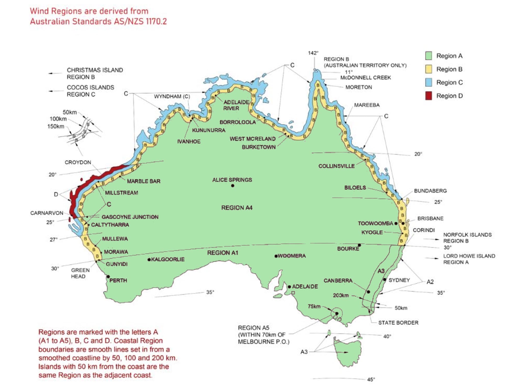
- The wind region; A, B, C or D. Wind region’ refers to the classification of different regions of Australia, based on wind speeds and frequency of extreme weather events experienced in those areas. These regions have been determined according to the Australian Standards AS1170.2 Structural Design Actions.

Region Wind Speeds Vs m/s Vp m/s Vu m/s A 38 41 50 B 38 49 60 C 45 57 70 D 50 69 85 - The terrain category of the installation site is another important factor in pole design and engineering. It relates to the area’s exposure to wind as a result of the surrounding terrain.The terrain category rating indicates the obstructions or surface roughness associated with the particular terrain, which will have a direct effect on the wind loading on the pole and its operating equipment.Selection of the terrain category is made with due regard to the permanence of the obstructions that constitute the surface roughness. For example, the vegetation in a tropical cyclonic region should not be relied upon in assessing the surface roughness during a wind event. Typically, the larger the obstructions surrounding the installation site, the less the wind loading on the pole and vice versa. These factors are also affected by the height of the structure via the terrain/height multiplier.
The terrain categories utilised in pole design are as followsTERRAIN CATEGORY 1
Very exposed open terrain with very few or no obstructions, and all water surfaces (e.g. flat, treeless, poorly grassed plains; open ocean, rivers, canals, bays and lakes), measuring 10km radius or more.
TERRAIN CATEGORY 2
Open terrain, including grassland, with well-scattered obstructions having heights generally from 1.5 m to 5 m, with no more than two obstructions per hectare (e.g. farmland and cleared subdivisions with isolated trees and uncut grass).
TERRAIN CATEGORY 2.5
Terrain with numerous, closely-spaced obstructions, usually between 3 and 10 metres high. This terrain category usually relates to suburban, built-up or densely wooded areas.
TERRAIN CATEGORY 3
Terrain with numerous closely spaced obstructions having heights generally from 3 m to 10 m. The minimum density of obstructions shall be at least the equivalent of 10 house-size obstructions per hectare (e.g. suburban housing, light industrial estates or dense forests).
TERRAIN CATEGORY 4
Terrain with numerous large, high (10m to 30m tall) and closely-spaced obstructions, such as large city centres and well-developed industrial complexes.
- The total effective sail area of the lighting or other equipment to be installed on the pole. For each separate light fitting or piece of equipment, the largest single surface area, as well as the drag coefficient of the equipment, are taken into account in assessing the loading on the pole.
- The mounting height(s) of the equipment on the pole.
- The total weight of the equipment being mounted on the pole.
- The offset of the equipment from the pole centre.
- The Topographical Multiplier is also termed the ‘hill-shape’ multiplier measures the effect of topography on the wind speed. In determining the wind speed, it accounts for the topographic effects on wind speed by using the ‘speed up’ factor or ‘topographic multiplier’. The wind speed at a given position on the hill is estimated by multiplying the speed up factor with the value of the upstream wind speed.
- The Shielding Multiplier adjusts the local wind speed to account for the shielding effects from upwind buildings that are either taller or the same height as the pole being considered. Terrain categories help to define the shielding objects. The slope of the ground is also a factor that influences the shielding effect.
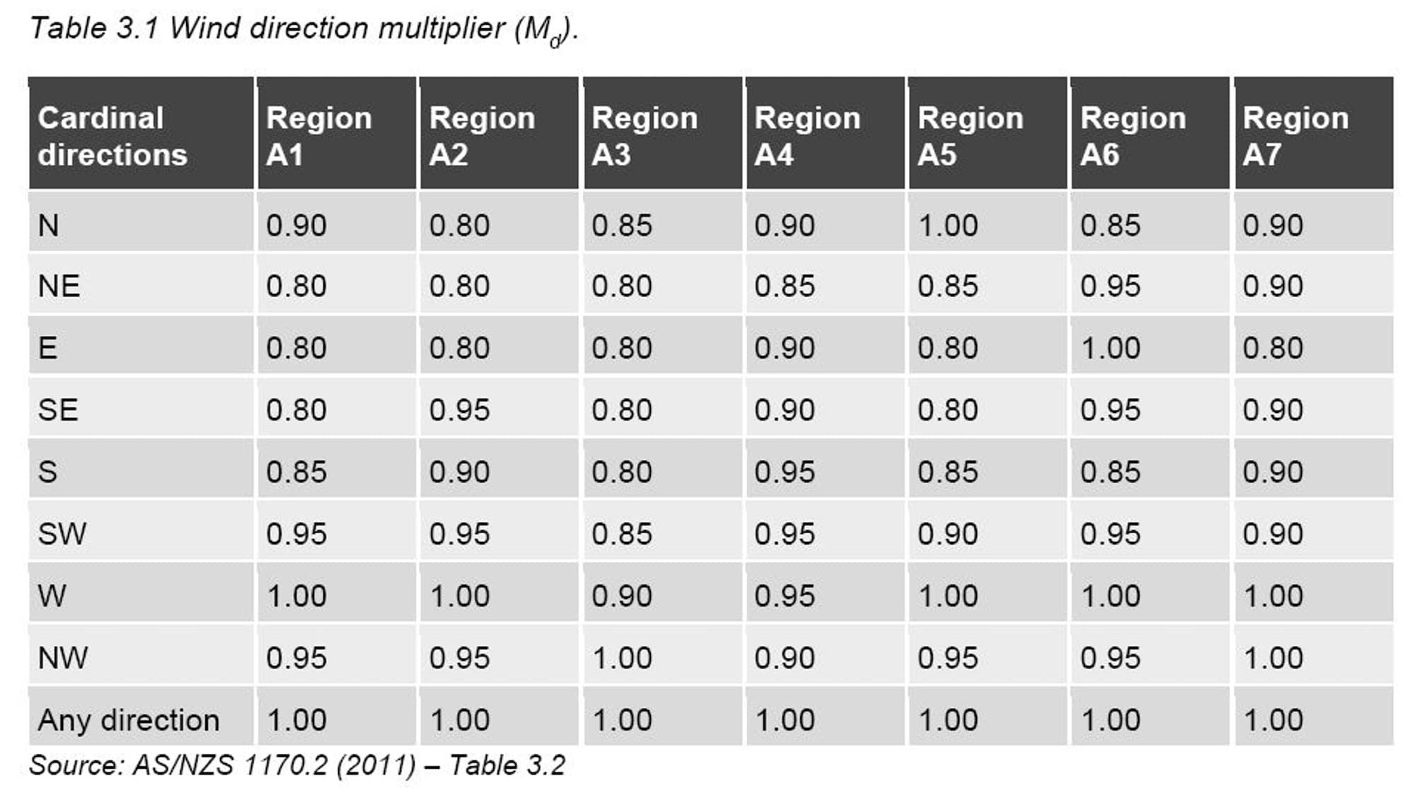
- The Wind Directional Multiplier based on the AS/NZS 1170.2 has been developed by considering a limited number of Bureau of Meteorology (BOM) weather recording stations across Australia, mainly at airport locations. It calculates the wind direction multiplier based on wind speeds and directions extracted from climate simulations.The regional wind speeds for each of the four wind regions, A, B, C & D are the maxima across all wind directions. For Wind Region A, AA1170.2 enables this wind speed to be reduced for some directions as per the below table.
 In regions B, C and D, tropical cyclone and thunderstorm gust wind speeds dominate the extreme high range tail of the wind speed distribution. The prevailing direction effects from tropical cyclone and thunderstorm gusts are small, so AS/NZS 1170.2 recommends a value of unity for all directions as the wind direction multiplier. A single statistical direction multiplier of 0.95 is given for overall forces and loads for major structural elements.This value is used in conjunction with other values to calculate the site wind speed (i.e., variables such as: Wind direction multiplier, terrain/height multiplier, topographical multiplier, etc.
 - The Annual Probability of Exceedance as per AS1170.2 requires that regional wind speeds of specific probability be used for pole design. The more important the structure, the less the allowable risk that the design speed will be exceeded in any one year and the higher the speed required in design. The Annual Probability of Exceedance for Wind Speed is selected from the various tables found in AS1170.2 and the building code.
